Layout of a Minefield
| < Electrical Control of a Mine | Δ Index | The Submarine Mining Station at Port Laing > |
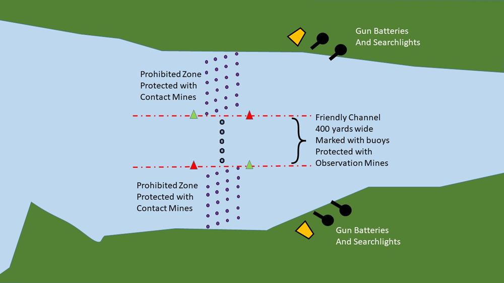
As described earlier, a typical minefield consisted of a 400 yard-wide friendly channel, guarded with observation mines, and flanked by electro-contact (EC) minefields.
Lots of experiments were undertaken to determine the optimum spacing of both types of mine.
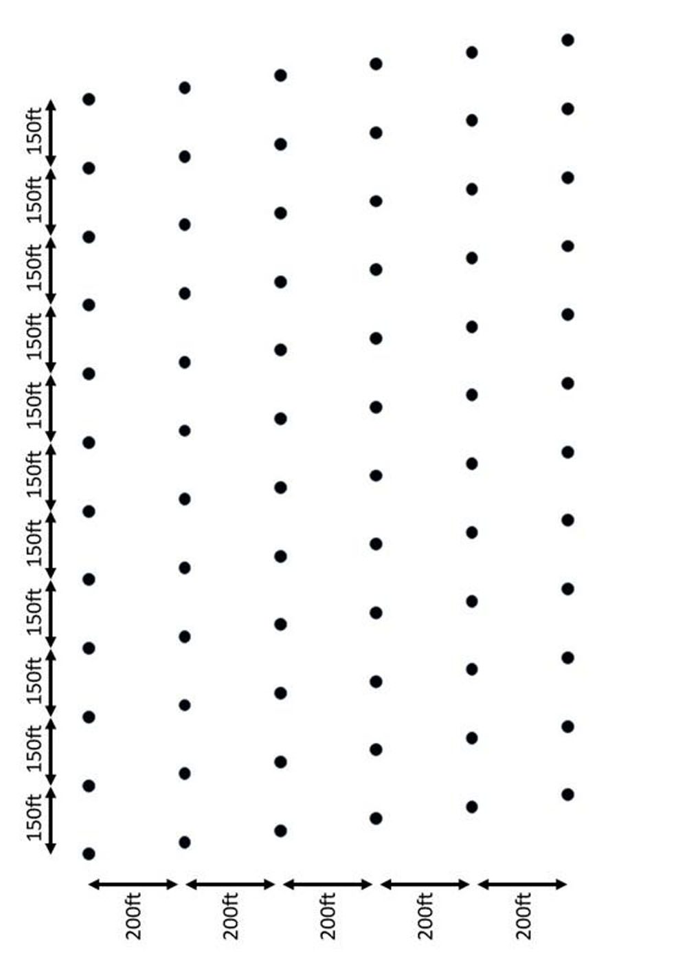
The electro contact minefield was laid out so that there was effectively one mine every 25 feet across the estuary.
However, the mines could not simply be laid out like beads on a string, because the explosion of one mine would then trigger the detonation of adjacent mines and ultimately blow up every mine in the minefield.
It was determined that these mines had to spaced at least 100 feet apart to prevent this sympathetic detonation. So the Electro Contact minefield was laid out in six rows 200 feet apart, with the mines in each row 150 feet apart.
This gives the desired effective spacing of 25 feet between mines across the estuary.
Connecting up the EC mines
The earliest form of Electro-Contact mine, as described above, used a momentary-action contact-closer in the mine (i.e. the switch was only closed for a moment when the mine was bumped) and needed a dedicated cable to connect each mine to its associated shutter box in the shore station.
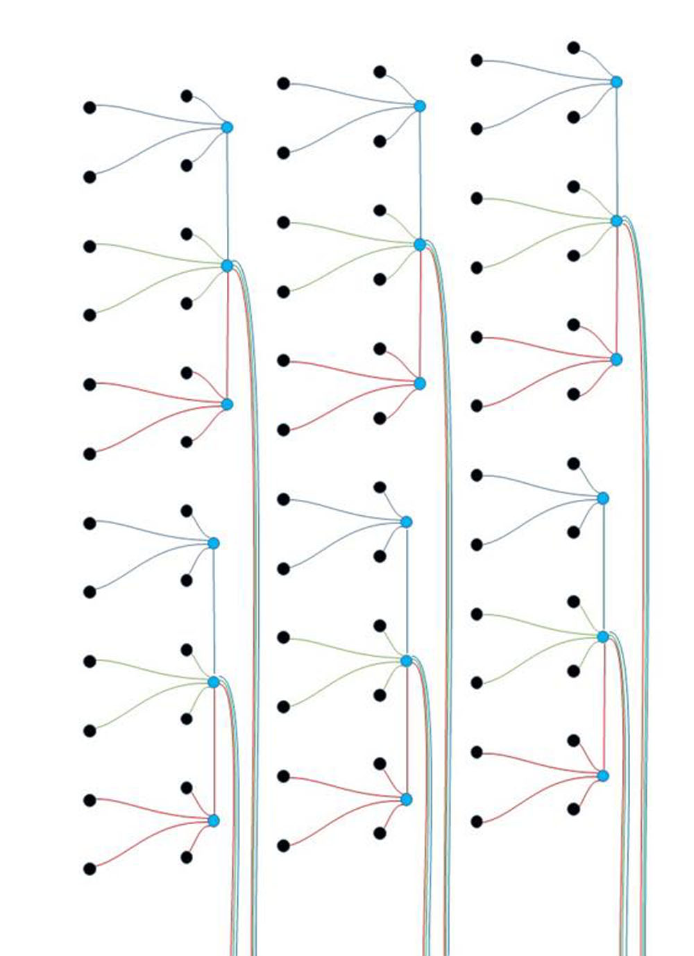
A later version used a “polarized relay” in the mine. This acted as a “latching switch” i.e. when the mine was bumped, the switch closed, and stayed closed.
This new design allowed four mines to be connected to one cable, and managed by one shutter box.
Connecting Observation Mines
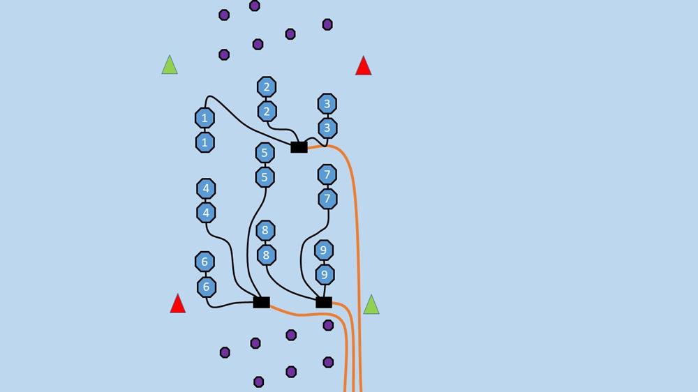
This diagram shows how observation mines were laid in the friendly channel. They are spaced so that it is impossible for a ship to thread a safe passage between the mines. The observation mines were deployed in pairs, each connected to one firing switch.
Two smaller mines fired together gave the same coverage width as one much larger mine. Two smaller mines were easier to deploy, and also the smaller blast radius made them less likely to affect other mines in the vicinity – especially contact closer mines outside the friendly channel.
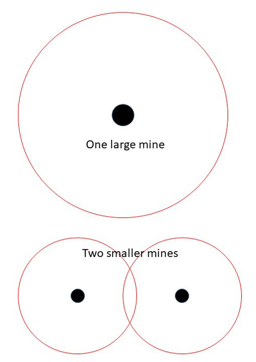
The observation mines were connected to the shore station through a four-core cable which terminated in a submerged junction box.
From each junction box, three single-core cables each connected to a pair of mines. One of the cores in the four-core cable was left as a spare in case of faults in manufacture or damage on installation.
Observation stations were placed on shore abreast of the mines, if possible at a height above the water of 1/60 of the distance to the furthest mine.
[The Carlingnose Observation station is about 125 feet above sea level. It is about 7000 feet to the shore at South Queensferry, so the far edge of the friendly channel was perhaps 5000 feet away. The height is then 1/40 the distance to the farthest mine.]
Mooring Observation Mines
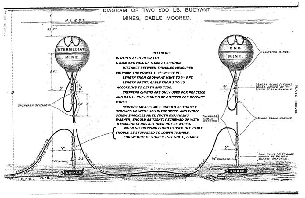
This diagram shows how a pair of observation mines were deployed. These are buoyant mines for use in deep channels. They are moored to sit well below the surface (35 feet or approx. 10.5 metres) so that ships can pass without dragging them out of position. In shallower water, they would sit on the sea bed.
Electro-contact mines were moored in a similar way, but were moored much closer to the surface so that they would be struck by passing ships. During the day, the electro-contact mines could be dragged out of position if friendly ships wandered into the no-go zones. The minefield was tested daily to ensure everything was connected properly. Faulty or suspect mines could be retrieved and replaced, or divers could be sent down to inspect the mines in situ.
| < Electrical Control of a Mine | Δ Index | The Submarine Mining Station at Port Laing > |
top of page
